I should take a little detour here, and say I picked up an antenna analyzer. The (fill in the analzyer model). I found the whole process of hooking up the radio to low power (1Watt) and finding open frequencies, and keying up, calibrating the SWR meter at each frequency, and iding a tedious pain. How much easier it was to see! the SWR curve with a quick sweep! And to make adjustments and see the changes instantly instead of gathering 3-5 new frequencies. Also, the higher element count antennas have non simple SWR curves (as you can see from the 8 element quad in a previous post)
Back to the antenna building process. Trimming brought the resonance closer to what I expected from the simulation, implying that the electrical length of the element was a little longer than pressumed by the simulator (or my soldering an N-type connector with a wire wrapped around the dowel added some extra capacitance)
So the next order of business was to build a 3 element yagi to test how the spacing behaved. I figured the copper shouldn't affect the spacing too much. It resonated a bit high, which lead me to the conclusion that the elements shoudln't be shortened quite as much as the dipole indicated. Probably that extra capacitance from the conenctor. So I decided to try adding some length by putting a small length of tape on the ends to lengthen it. Seemed to work! So a lot easier than the quad which would require an entirely new wire to lengthen an element. And I was too excited (and as always, short on time) to stop and take build pictures as I went.
One detail to work out was mounting the to booms. But I'm going to save the rest of the story for a followup post.
Entry for February 23, 2019
As always, overly distracted actually playing with amateur radio instead of writing about it. But here goes.
I'm using the dual band cubical quad somewhat successfully. It gets me up to LA on 2m ssb, but it's really unwieldy to get in and out of the car, and I've given up trying to tune it for 446. So with that, I've decided to stick to monoband antennas, and build another 2m beam anteanna. I also want something that's easier to get in and out of the car. So with that in mind, I decided to switch to a Yagi split beam configuration. I've been designing and building it for the last couple months. There just aren't enough evenings free! I'll have more of a write up about it once I've tested it a little, but so far it's much easier to get in and out of the house (too much metal in the house to test indoors). So far it's been an interesting balance between RF ideals, and practical mechanical considerations when bringing it to physical form.
In other news, there was another ARISS SSTV even at the tail end of January. And I really wanted to go this scheduled group desert hike out in the Anza Borrego Desert. So I ended up getting taking advantage of a nearly direct overhead pass while I was on the trail, and managed to pull in two images using nothing but my UV82HP, a telescoping dualband antenna that collapses into my jacket pocket, and the phone held up to the speaker mike to decode the image.
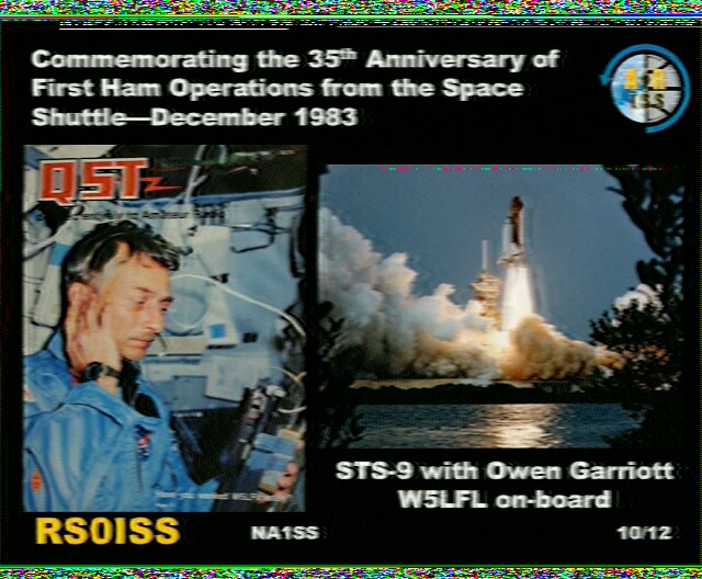
And of course I submitted a report and recieved a certificate for doing so.

Of course I completed some other attempts at home with my first 2m cubical quad. It's important to remember that the ISS orientation can vary, and that sometimes one has to rotate the antenna to match polarization. For one of my passes, I was holding the antenna rotated over 50 degrees to get a good signal. Compromised how much height I could get, but it still worked well enough to get a couple more pictures.
Entry for September 23, 2018
Well I'm still chasing down the gremlins in that dual band antenna build, but I think I have made some progress. At the very least, I can get the simulation results up, and some pictures showing it and the construction details I have been asked for over the air.
I think part of my problem comes from chasing high gain and wide bandwidth.
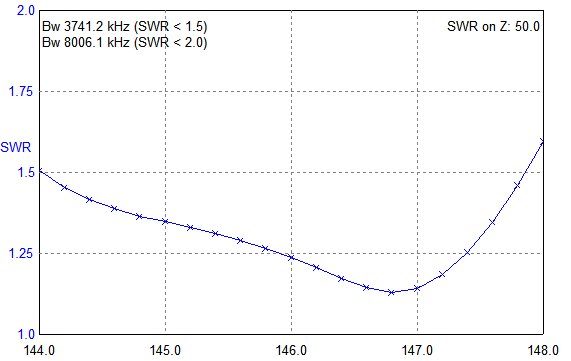
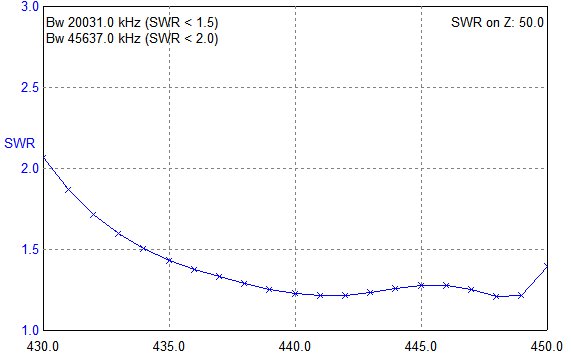
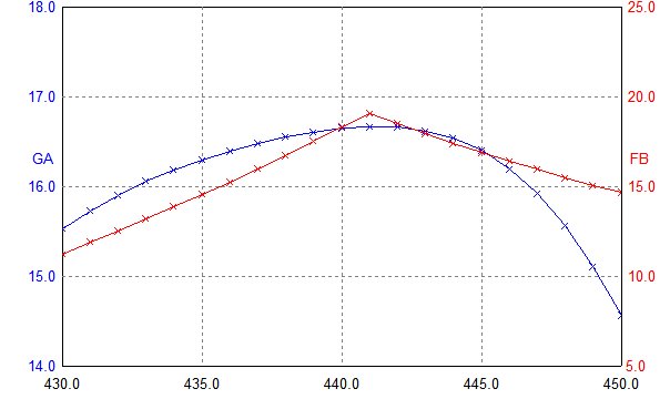
As you can see from the simulation results, the resonance falls off rapidly on the band ends, which is of course where I want to operate. This leads to more sensitivity observed due to the elements getting bent and set up varability. In addition, the resonance seems to be low. One thing I neglected to take into account, is the small spacing in the connector 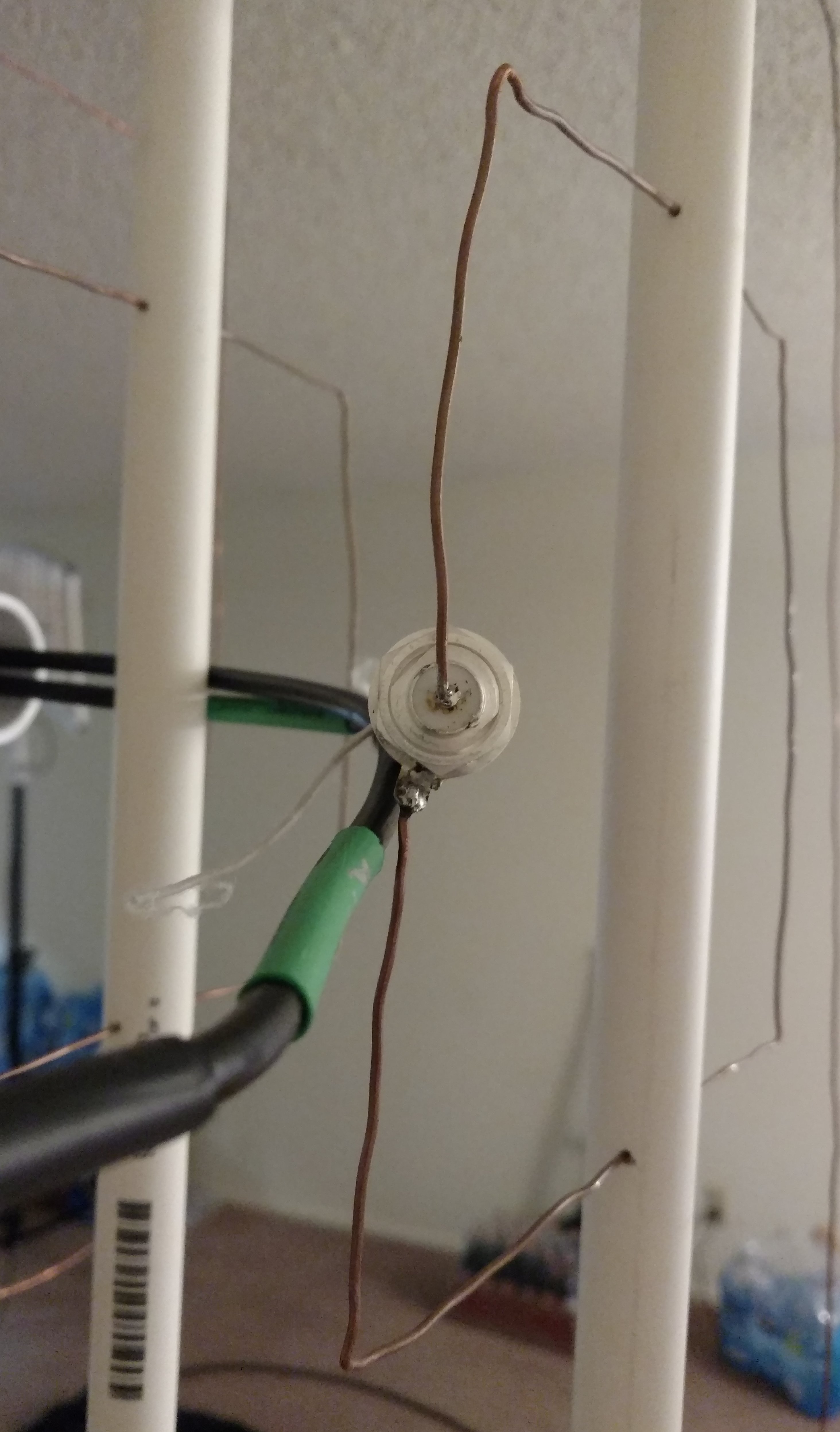 I think leads to an additiinal 3/8" effective length to the driver. I took the driver apart and trimmed off about that much, and am now getting the 1:1 point closer to the simulated frequencies. Director one on 70cm also seems to have come out slightly long, though I havent looked into fixing that just yet. Anyways before I get into some of the other construction details, here is the behemoth!
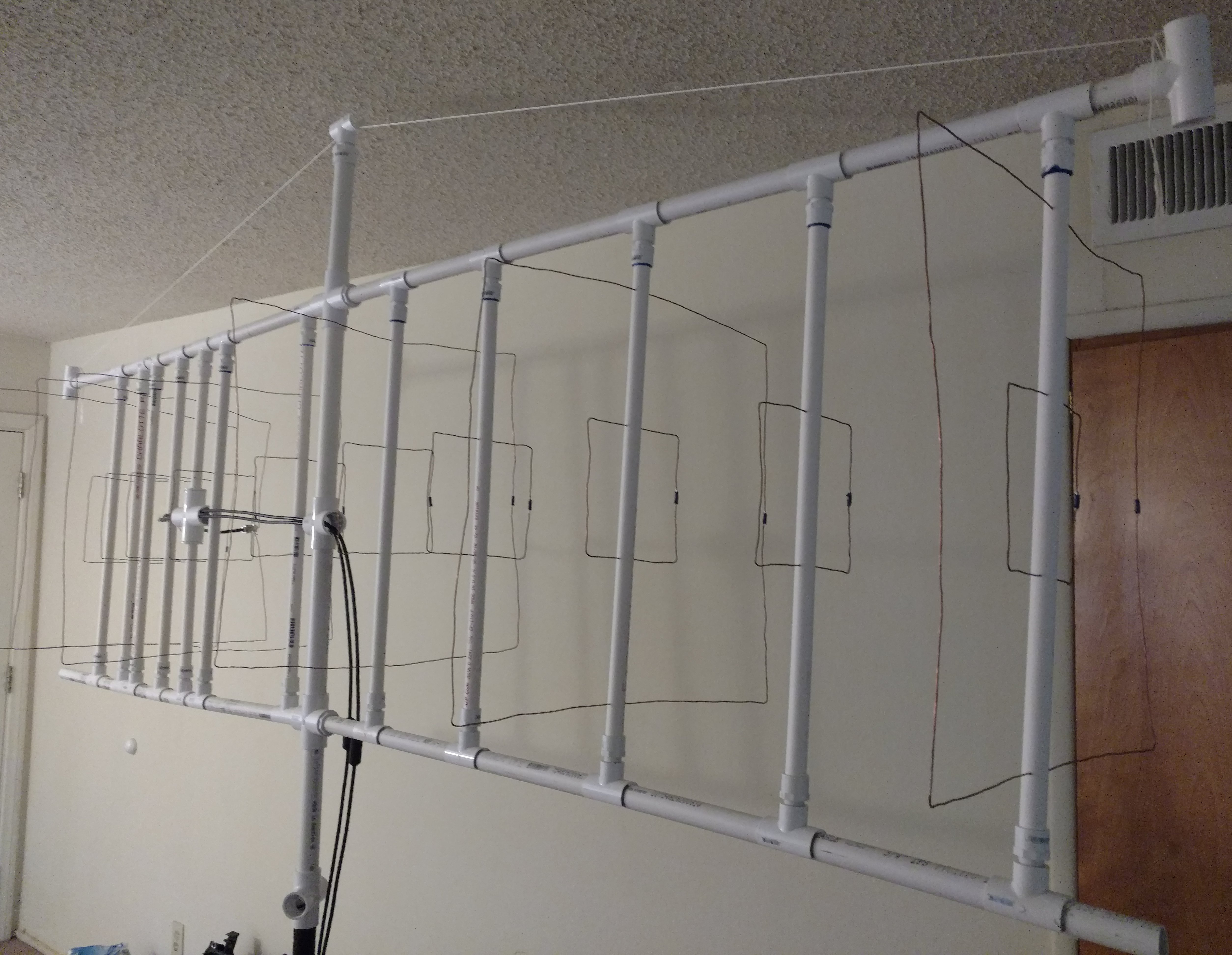
I know it was going to be long from the simulator, but reading 82 inches on the screen, and actually having 88 inches of antenna in front of you, are two different things. I ended up swapping the schedule 40 booms out for the thin wall 3/4" pvc pipe to lighten the load. The schedule 40 was sagging anyways. And you can see the twine stay to help hold up the ends. In thise design, I also used butt-splices to bring the ends of the loops together instead of my previous technique of bending the wires around each other, soldering the elbow, and then snipping off the execess. I felt this would allow me to control the lengths a little easier. I also used a metal yard stick from Lowes to measure the wires instead of using a tepe measure. I think it was easier and more accurate.
And now of some more details I've been asked about over the air. Here we have the adjustable element position techinqe. I am using 3/4"x1/2" snap tees. These snap on and can slide around a standard 3/4" PVC pipe, and have a 1/2" thread port perpendicular to the boom.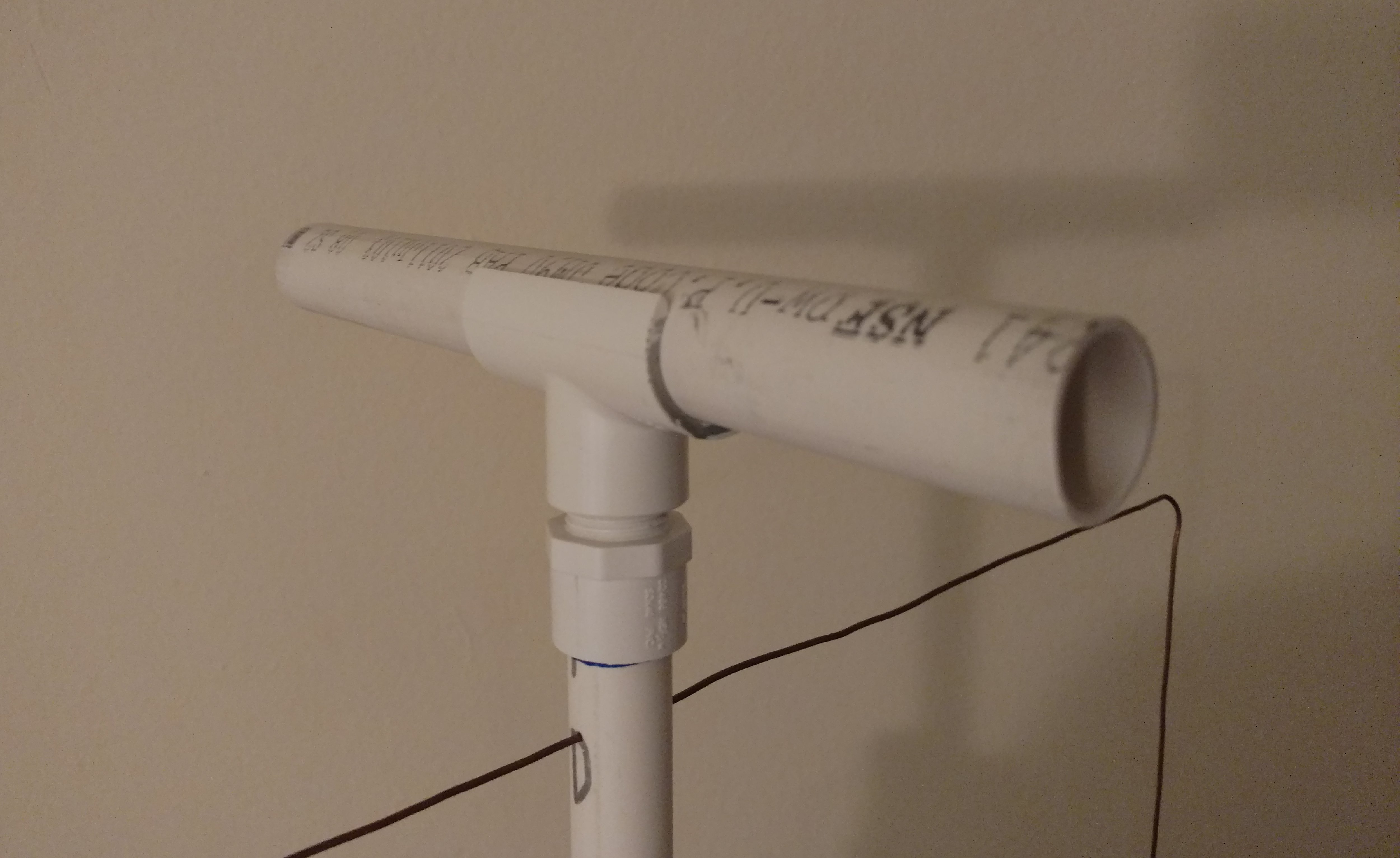 So using these, I can position them, and tweak the positioning to coax the resonance to my operating point. I mark off the common positions so I can quickly reset up if (ok when) they get knocked around in the car.
 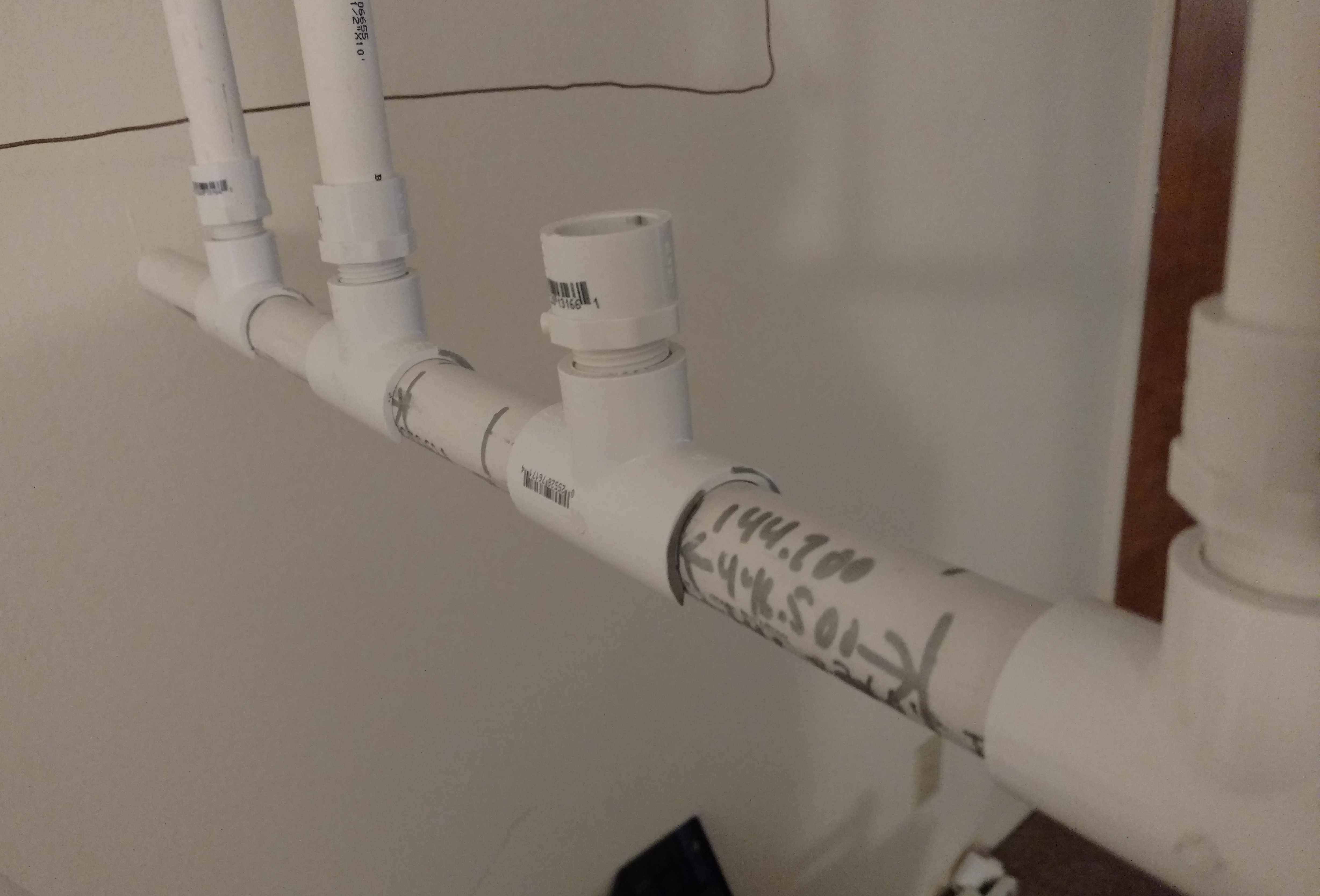 . The snap tees have theads in them, so I put in a 1/2" thread to 1/2" slip adapter to mount the actual pvc support for the wires. This has the added benefit of allowing me to turn the elements in place, to parallel the boom. This means I don't actually have to dismount the elements from the booms for transport. A real time saver! I also have the antenna broken into to halves, which adds to the sag problem. But it means that I only have 48 inch sections to stick in the car,instead of the full 96 inches.
Well that's it for now, find me on the air, or e-mail me if you have questions. Use my call sign at my call sign dot radio (have fun SPAMBOTS)
Entry for September 16, 2018
Recent adventures include building up a dual band cubical quad for 2m/70cm use. It was targeted at wide band coverage to include sattelite and FM repeater zones, at the expense of a little bit of gain. Well I sort of underestimated the behemothness of it. I'll post pictures another time, as well as some simulation profiles (hopefully I don't get distracted again), but suffice it to say that it's a bit big and therefore not too useful in the satellite arena. The other mystery I'm tracking down is why it seems to have downshifted in resonance by a couple MHz on both bands a week after initial build. More on that when I have more information
In other news, I ran my first net this week. The weekly Greater Los Angeles (and San Diego) Emergency Simplex Net had a missing fill in net controller (Hey we have to give K1KMO a break every now and then), so given that propogation was such that I seemed to be in the best position to hear stations, I was nominated to take over. I had 14 check ins (all from around the LA area), and most of them were direct. It was a good exercise in what can happen during a real Emergency, and demonstrates that everyone can and should be ready to quickly step in when needed. And sometimes it won't be the station that one would expect. So I suppose here is the list of checkins as I have it:
Checkins for the Greater Los Angeles (and San Diego) Emergency Simplex Net for Wednesday, September 12, 2018
- K8NBD
- KM6NAO
- KM6IQQ
- KI6LOV
- K6OLI
- KM6KAO
- KE6FVN
- KM6LKW
- KM6LDQ
- KM6IGY
- KM6FVH
- WA6JFK via KM6LDQ
- K6CSB
- W6GSW via KM6LDQ
- KK6UXB
- KK6WLD ME! Net control
I have to say that propogation has been pretty good all summer this year. Well depends if you're trying to do relative DX simplex or work the local repeaters. LA area repeaters have been carrying down and in some cases wiping out local San Diego area repeaters all summer. Just this week, I had to pull out the beam to listen to a local net on the 145.180 MHz repeater that is about 10 miles away. Why? Because the repeater up in Pasadena on the same frequency was overpowering the signal at my QTH. Stuck Pasadena in the null, and the local Woodson repeater could overpower it then. But on the simplex side, it's been awsome to be able to hear the majority of the LA simplex net, and participate directly to net control. It's also a lot of fun to be able to relay LA stations back up to LA.
Entry for June 9, 2018
So thanks to Tim (AG6RS) for pointing out to me, that I have yet to post up a write up of the version 3 (2nd to make it into use) 70cm antenna that I built towards the end of last year. So here goes:
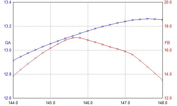
I'd had a lot of fun making it into the Greater Loss Angeles Emergency Simplex Net with the 6 element cubical quad below. But there were a number of weeks that I could hear the net going on and LA stations could hear me keying up, but just couldn't pull me out of the noise. And So I thought I would build a better antenna with more gain to get up over the noise. I origionally planned to build an array, and in fact made the elements for a 2up 8 element array. But after some research and through, not to mention mixing and matching of elements from both arrays, I ended up going with a single. The 2nd beam would in theory get me about 2.5-3db, but I would need a matching network, and more mechanical grief. I decided in practice, I wouldn't probably get much return for a lot of extra effort. Plus I had good performance with the single 8 element, and because it was computer optimized (well with a little human help where the optimization algo would get stuff in somewhere land), it actually has a lot more gain than the previous 6 element, which was taken from web site design. So here's some pretty graphs from the simulator.
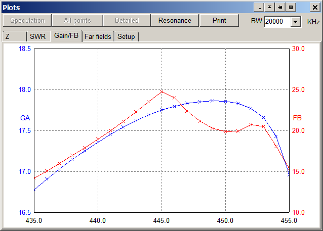
Now in testing, I noticed that while the gain did improve ~5-7dB over my previous antenna, the F/B ratio was pretty bad still. The previous one didn't simulate with good front to back ratio, and while at first I thought I didn't really need it, it turns out that with Mt Soledad directly behind me, about 4-5 miles away I was getting some interference from something up there. So I took to hunting that down. After carefully measuring everything and simulating the as built parameters, and finding that the little tab on my tape measure had more give in it than it's supposed to (resulting in 3/16" longer elements than intended), I finally threw my hands up and thought the only difference between practice and simulation is the corners. Because I bending the wires around my finger, they are slightly rounded. Could rounded corners be bad for function? Well turns out there are. Here is a simulation with simulated rounded corners (ok, so just a octagon). 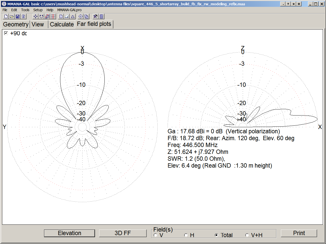
 And sure enough when I carefully squared up the corners on the antenna, the F/B ratio went up by 3-4 dB, without a corresponding drop in gain (hooray for insanity checks).
So here is an actual picture of the result taken with the phone. 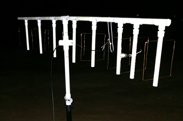 I'll try to get a better picture up taken with the DSLR as with the previous antenna at some point.
Entry for April 23, 2018
I submitted my best SSTV image from this month's ARISS SSTV event, to recieve an electronic award. There's still time if you managed to snag an image of your own. In the mean time, here's what it looks like:

Entry for April 21, 2018
Well I've finally gone and done it! I have a regular domain. My Ham activities will be chronicaled at http://kk6wld.radio. The old url should remain valid for the foreseeable future
Entry for April 13, 2018
Quick entry tonight. So for the last couple days, the Russian side of the space station has been transmitting SSTV images commemorating 40 years of their Interkosmos Project. I got delayed coming home from work, but I was able to meet up with a few people via the radio on the Woodson repeater. I didn't catch their call signs though since I was hurrying home, but I'l stll give a shout out here to KJ6SJY and K6ANA. Sorry I didn't get everyone else's callsigns in memory or written down. I missed out on getting a good shot at the first of the two images transmitted during tonight's pass over San Diego, but here it is in all the glory possible from a cell phone sitting on my driver's seat listening to my QB-25 mobile radio as I ran inside the house to get my real set up going.

And here's what I got using my cell phone up against the speaker mike of my Baofeng UV-82HP, hooked up to my home brew 6 element 2m cubical quad.

Happy hunting everyone! There's a couple more opportunities tomorrow!
Entry for April 2, 2018
No more TRAM stuff. My first mag mount antenna was a tram, I forget the model number. And it worked barely better than the rubber duck on the HT inside the car. I took it apart after I got the Diamond 7500 on the MFJ tri-mag set up, and found that the TRAM assembly was horrible. At the base where the coax center conductor was clamped to the base, most of the clamp was around dialectirc, with a couple whiskers of the center conductor actually making contact. I'm surprised the SWR meter didn't throw a fit. But anyways back to tonight. I picked up a TRAM NMO-UHF adapter to try out my tri-band antenna for 220 MHz work. And before I went crazy, I decided to put the dummy load on it first. And the SWR meter read 1.7!. Into a dummy load. I put the Diamond 7500 back on the NMO mount, and guess what? Only 1.3! After two years an the roof of the car (and probably close to 50k miles, it still reads factory fresh. And yes, I did check the dummy load straight on the back of the SWR meter, and it dutifully read close to 1. Ugh! So I guess back to HRO I go, and pay up for the Comet. It's double the price, but I am not starting at an SWR of 1.7.
Entry for March 25, 2018
So I've been having wayyyy too much fun playing with antenna's and Radios to actually sit and type here. But because Matt (KM6BSB) keeps reminding me that I should share my experiences with the rest of the world (all two of us that read the ramblings on this website), I've taken a moment to type some stuff up. I'm not going to try and pick up all the stuff over the past 8 months (wow!). Instead, I'm just going to jump to my current activities, and maybe some day the others will get some more attention. This month, I aquired a couple new radios. On some reccomndations, I picked up a Radioddity QB25. I'm going to save my rant about that one for another entry. The other was a 10w handheld that I'd been eyeing for a while, and bought on a spur of the moment because EBay had a 20% off EVERYTHING coupon. Ugh yes I succumed to that. Anyways this entry will focus on the TYT UV8000E that I've been playing with this week. Well this weekend. You see, I couldn't play with it earlier this week because well, there's no Chirp support for it. Been on the list for over a year and a half, an no dice. Now you might say that it comes with software and that's that. Well yes. It does. But I have all my repeaters programmed in Chirp. And it's really nice that I can copy and paste them around between the various versions of UV-82, and the QB25. But not so, for the UV8000E. So since the UV8000E software has a nice spreadsheet looking tab for entry, I figured no problem! Copy and paste across applications. Nope. It doesn't implement copy paste from the clip board. And there's no .csv import either. SIGH! So what's a ham to do? Spend a couple hours keying all 500 frequencies? That's 128 entries, with an uplink, downlink, xmit PL, and recv PL! Or spend what ended up being 7 hours to write quick dirty C program to parse Chirps csv output, and write it in the UV8000E dat file format? Well obviously the later.
Now that effort itself was a bit frustrating. I'm not going to get into the silliness of the data format, but suffice to say, it was not quite consistent, and had some fun doh's to it. But at the end of yesterday (ok it was 1am this morning) I had a program that would take the header from a real UV8000E dat file, convert Chirp CSV output into the apprpriate binary mangled format for the dat file, and then take the relevant parts of the rest of the file that represents radio specific config. So I can edit the config as I see fit in the TYT software. Then dump out my latest and greatest repeater list (I REFUSE TO USE THE TERM "CODE PLUG"), and after running my C program, get a dat file that I can load into the TYT software, and throw up into the radio! Needs a couple refinements, but I plan to post a link to the source in a future edit. Who knows, maybe I'll even put up a binary and a readme. I write it under Cygwin, so I have no idea of the .exe will run under normal windows, or if it maybe has the dll in with it. It's in pretty standard gcc friendly C, so it should be compilable on most platforms.
Oh and the UV8000E? It's got some nice features. Feels nice in the hand. Supposed to have priority transmit config, and dual recieve, though I haven't gotten that for in my testing. I have found some irritations though. Even though you can use your usual Baofeng compatible programming cable and headsets, don't push the A PTT. The radio only has one PTT button, and if you push the APTT, it resets the radio. Ugh. Oh. And if it has crossmode enabled, and there's a signal on the input, you can't do anything except power it off. I ended up having to pull the antenna off, so I could disable it on the radio since I was away from my computer. I've got to disable that in the template my program uses to generate a merged file. Let's see, FM radio has some clicking when you're actually having it watch the HAM side, and it doesn't tell you what it's watching. And while it's nice having seperate indicators for which side you're working on, and which side has an active signal, would it have killed them to use the larger of the two for the active signal? I can't see it without squinting with it right in front of me. And I do QFN soldering at work! Anyways. Verdict is still out on this one, though I guess it's not so bad that I'm already returning it. Besides! I have 7 hours invested in a conversion program for it. Next time... my experience with the QB25!
Entry for July 27, 2017
So it's been a while since I've updated this page. Lots going on including some radio stuff. Been having some good luck with the Simplex Net out at the Torrey Pines Glider Port by UCSD, but not so much at the home QTH. But that's not the main object of this post. Nope for the past month I've been slowly rebuilding my 2m version of the Cubic Quad. I built one up for Field Day (which I still haven't written up either) and had a little success with that. But it was a bit cumbersome and also got damaged by something in the yard over night so I've changed the design a bit and have a new version. I've switched to using wooden dowels for the boom and wire supports. The supports are horizontal instead of vertical, and the wires are in a square configuration instead of the diamond I used on the 70cm quad. This makes the antenna take up less space (I can fit it through the door as a unit, the diamond had to be completely dissassembled).
So the goal this month was to build up the antenna to participate in the i 20th Anniversary ARISS event. I downloaded the Heaven's Above app for my phone to calculate and plot the ISS passes for my QTH, and then spent last Thursday night through Monday morning running out with the quad, and my UV-82 to try and catch the pictures. And catch I did. Got almost all 12 (missing part of image 8). Got to experience a lot of excitement tracking the station, and trying to maintain the signal lock. I got lucky on the first few passes that my vertically polarized quad was the way to go. Later in the weekend, I had to start tilting over the support so that I was more diagonally polarized. Anyways, wanted to get this up, so I'm keeping it a little less detailed than previous posts. But if there's interest, I'll do some more writing (and picture posting).
Entry for April 12, 2017
Well propogation tonight wasn't great. Only heard W6RIP, but that was enough to still have some fun and to run some more field tests on the Beam. Assembled it in about the same spot as last week during the PAPA System New Ham Net, and checked in to PAPA 4 with KK6LMC who was running net control. My one watt was till making it clearly, so that was a good sign the antenna suffered no ill effects depspite having a bent element (I un bent it as I assembled it).
So off to the simplex net, and I aimed a little bit or right of where W6RIP's signal seemed strongest (and using my compass that seems to have ended up a hair west of North, although I'm a little suspect of that and will have to check my compass at some point). Heard a bit of scratch during a couple station's check-ins (including KI6LOV), but nothing copyable. Kevin was nice and clear, although a tad weak (sorry Kev, you got wiped out a couple times with whatever local noise bursts that seem to pop up occasionally). No relays from San Diego (doubt there's many people trying from San Diego, but you really should).
Now for the interesting field tests. I did get the antenna switch (a Diamond CX210A) so I could switch to the more omnidirectional magmount on the roof of the car. After the net, I talked to Kevin, and he told me that he couldn't hear me when I switched to the mag mount calling for relays, but I was coming in clearly with the Beam. So that called for some more testing. First off, make sure the switch isn't bad. So I tried switching the ports and keying up PAPA 4 with the mag antenna with 1 watt. No response. Switching to FULL POWER (all of 5 watts! :) ), I got a return beep from PAPA4. I remembered the net feed, so I tried again, with the nice long delayed net feed and could barely make out my own call sign. Well looks like the beam's working wonders. But as I was putting things away, I realized there's a lot of loss along the way from my radio through the car to the mag antenna. The set up goes like this:
Radio with male SMA, male/femail right angle so female SMA to female UHF pigtail. This is constant for everything. Then I had the antenna switch with UHF connectors all around. Then there's about 15 feet of RG-58 that runs through the car with male UHF connectors on each end. I've got the cable coming out the drain plug in the spare tire well (don't like drilling holes), so there's a double female UHF coupler followed by a male/female UHF right angle to head towards the back. Then the 17 feet of whatever cable comes with the MFJ-336M mag base wrapped around the bumper a few times to take up the slack.
Ok so now you know there's a lot of loss through the car. To finish the story, I went and unhooked the antenna coax from the 90 degree UHF connector under the car, and hooked it directly to the SMA-UHF pigtail on my radio. And low and behold PAPA4 responds on 1 watt for me! Have to say though, it was only slightly less scratchy on the not very instant replay than the 5 watts was going through all that mess.
So my lessons for the evening: lots of room for improvement in my car set up (will have to research switching to N connectors, and maybe get a crimper so I can chop some antenna coax length off). Also, the beam does seem to help a bit, though obviously at the cost of having to aim carefully (yes I tested when I aimed more than 45 degrees off from Kevin, he went away).
Well that's it for now. Thanks again Kevin for all the fun. Till next time. One of these days, I really would like to get a map of my actual radiation pattern on that beam. Clearly it's got at least a few dB on the SuperGainer (which I still maintain is a great antenna especially compared to TRAM 1185 that was my first magmount, but that's a story for another day).
Entry for April 10, 2017
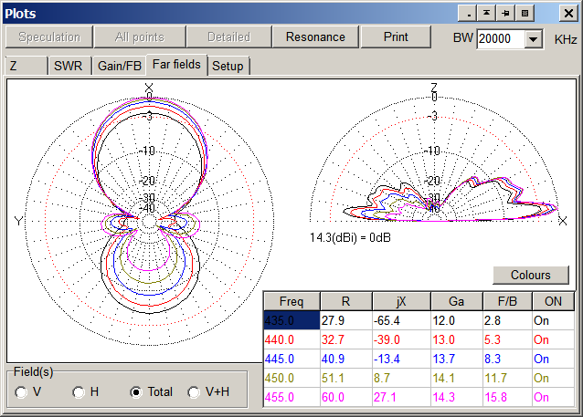
Well it's really a follow on to the April 5th one. I figured (and Matt (KM6BSB) wanted to see them) I'd add on some of the plots from the simulation that I hadn't put up last Wednesday night as it was getting late in the evening. So for your viewing pleasure:
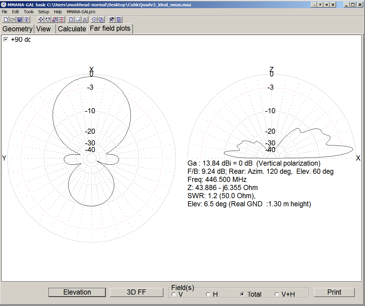
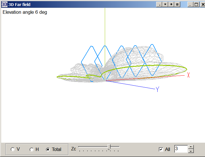
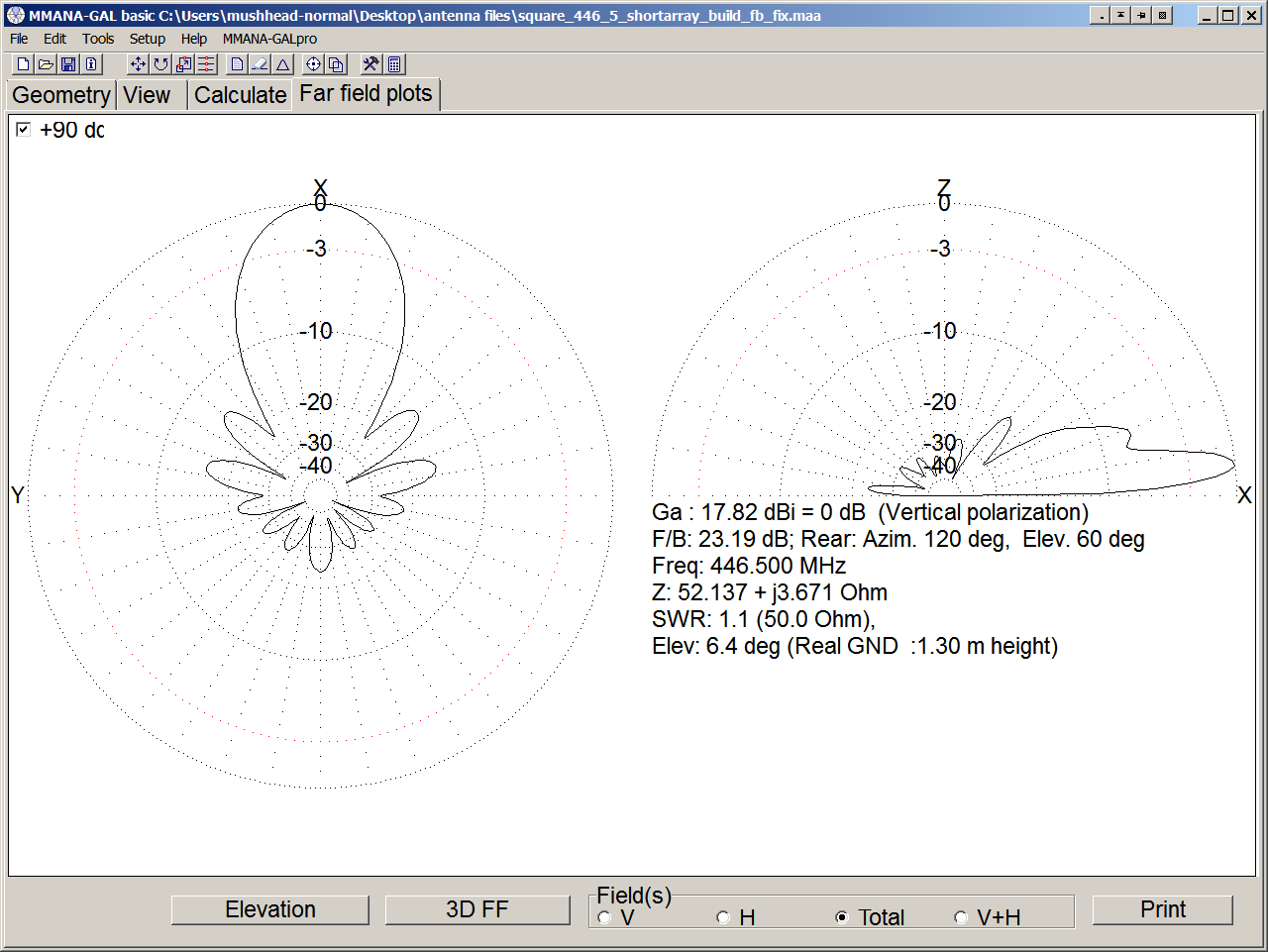
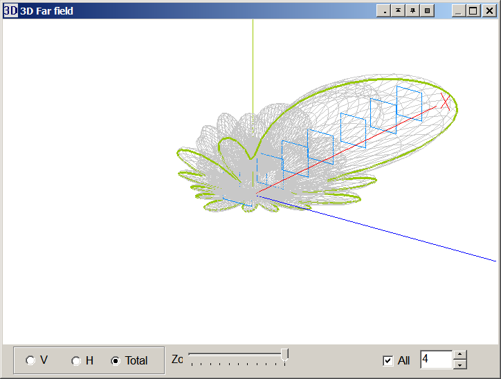
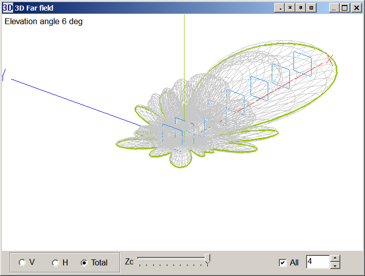
To get an idea of what the radiation pattern supposedly looks like, and where it's aimed. Sometime maybe I'll try to actually test out what it is in practice, but that's another weekend's project.
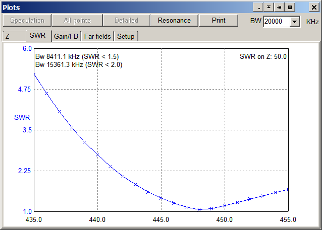
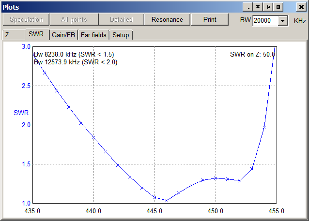
The modeled SWR plot is different from what I measured with the meter. Not sure what's causing the difference, and messing with the model hasn't yielded a closer fitting graph. Models are meant as a general guide anyways so PPPfffft!
NOAA's predicting some winds for Wednesday night, and some moisture. So we'll have to see if I bring out the beam again this week. Hopefully conditions will cooperate.
Entry for April 5, 2017
Well hello, and welcome to the start of my amateur radio page. I'm going to start out by saying that I'm not keen on fancy new web technologies, javascript, etc. I may start to use some of that eventually, but I haven't felt like teaching that stuff to myself, and frankly it annoys the heck out of me on other sites. So TOO BAD! I will stick to hand coding basic old school HTML for now.
That said, I'm starting this page for a couple reasons. One: Matt (KM6BSB) keeps bugging me to, and two: because of tonight's Greater Los Angeles Simplex Net. Propogation was awsome, but more importantly (well probably not, but it couldn't have hurt!) was the first field trial of my home built Cubical Quad Antenna. So without much further adu, here's a couple pictures!

There's the antenna in all it's glory from the location just off the glider port that I checked into the Simplex net tonight. You can see my normal Diamond mobile antenna on the roof. I've got the Quad hooked to a Baofeng UV-82HP clipped to the arm rest on the door. The radio's spec'ed for 7 watts on UHF, but only puts out about 5 watts on a fresh battery (had one this time), and run through a female SMA right angle, followed by a SMA to SO-239 converter cable.

So there's a close up of the elements, looking back up the array from the business end. The boom was aimed for best signal from W6RIP netcontrol for tonight's Net. And in posting this picture, I realize I had the reflector on backwards. Still seemed to work pretty well though.
I based the antenna on dimensions for 446MHz, although due to construction and measurement variation, a couple of the wire lengths ended up about an inch short. The simulation using MMANA-GAL Basic seemed to show the resonance up around 448-454 MHZ, depending on which of my measurements I used. But the my Diamond SX600 seemed to give me a my low SWR point of 1.1:1 around 440 MHZ. A couple forum posts around the net seem to indicate that running wire through PVC pipe can elongate the effective length of a wire, and I'm still working through the details of that, but could explain a little bit of difference. And my wires aren't very straight, so they probably are a little longer than my measurements might indicate. In anycase that's ok, it seemed in the right ballpark, and even had a 1.3:1 SWR up at 446 MHz. But, MMANA-GAL has an optimizer function, and given the purpose of this build was an awsome antenna for the simplex net, I ran the optimization with a focus on gain. The results generated some vastly different spacings for the elements, so I took those with a grain of salt, and some gut instinct (or just random assignment) and shifted the spacing between elements. Hooked it back up to the SWR meter, the SWR seemed to be very close to 1:1 right at 446.5!. Ran a few tests in the kitchen, then packed it up the next day (today) and re-set it up out at the glider port. Checked the SWR and it was actually still about the same. Woohoo!
All in all, it was a pretty good net. I heard 15 stations, including netcontrol W6RIP, and even could just make out W6TYL up in Tarzana. I'd like to thank KI6LOV and K6JSD for their signal reports and follow up comments. And of course K1KMO and W6RIP for organizing and running the net. I should also thank the PAPA System for running the VE sessions that allowed me to get my License, and for running the New HAM net that's encouraged me to stay Radio Active (and also where I found out about the simplex net). I should also thank my housemates (who's callsigns I may include later if they choose to be included) for putting up with the mess in the kitchen as I went through multiple itirations of each of the three versions of this antenna. It's been a lot of fun. Hopefully I'll be able to make it in more often even when propogation isn't quite as good. It's been an interesting few weeks' worth of evenings and weekends filled with measuring, cutting, bending, and soldering. Learned a few things (like get a nice big fat solder tip for soldering larger wire, and my 50 watt soldering iron goes from 10-38 watts in the last couple marks) along the way. I don't know when I'll update this page again, but with some encouragement, hopefully it won't be too long in the future.
Oh, and it looks like I succumbed to the modern age. I used a bit of CSS styling for tabs since I'm super lazy and didn't feel like hammering out white space code. Next thing I know, this site will have HTML5 Video!
Site contents Copyright 2017-2019 Gregory Reneff (strip off the -web). Offsite linked content copyright their respective ownsers.